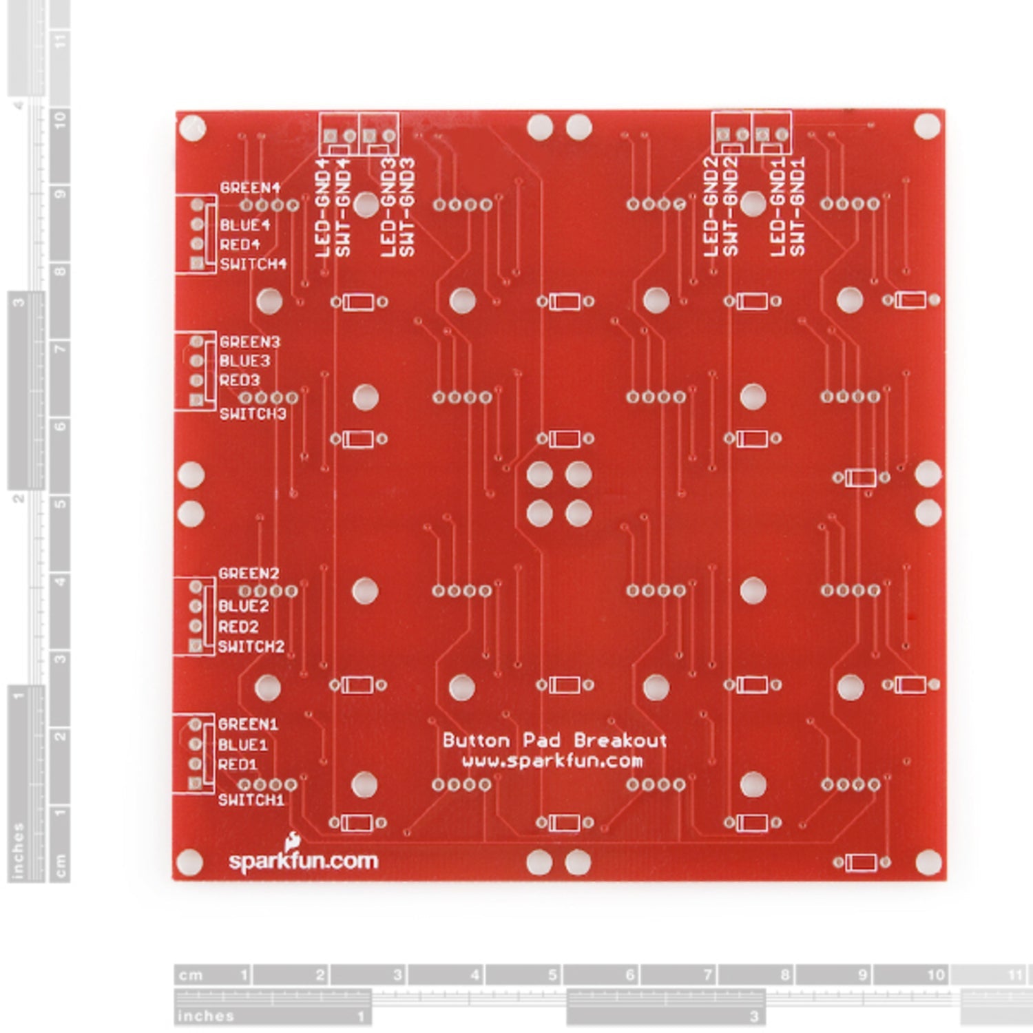
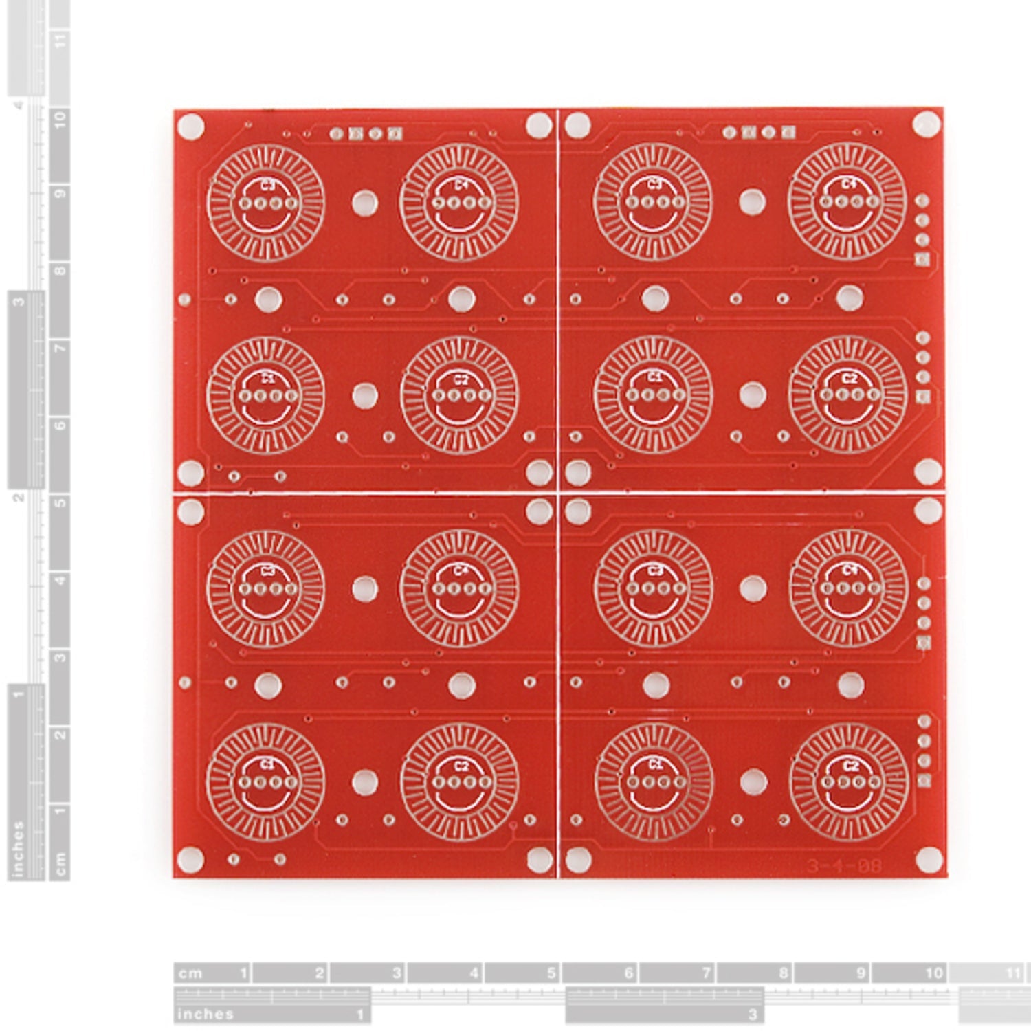
This is a straightforward breakout board for button pads. Each LED and button is connected to the side connectors, which are soldered on the back of the PCB. We suggest trimming the connector leads on the button side as short as possible to minimize pad deflection. Now, it comes with footprints for diodes! You can use the very affordable 1N4148 through - hole diodes. These diodes can isolate the switches, making decoding a bit easier. There are also useful documents available, including Schematic, Eagle Files, Hookup Guide, and Datasheet (CD74HC4511).


Using this 4x4 button pad breakout PCB is easy. First, connect your button pads to the side connectors. Make sure to trim the connector leads on the button side short to keep the pad stable. If you want to isolate the switches and make decoding simpler, use the 1N4148 through - hole diodes and place them in the provided footprints. When handling the PCB, be gentle to avoid damaging the soldered connectors. For maintenance, keep it in a dry place and check the soldered joints regularly. If you need more detailed information, refer to the Schematic, Eagle Files, Hookup Guide, and Datasheet (CD74HC4511) provided.